Building a Synth - Computer Music Tutorials,
updated for Reaktor v4.
The originial versions of these tutorials are available at the
Computer
Music Magazine website
Reaktor Tutorial : Introduction
This tutorial will show you how to build a simple
synthesiser in
Reaktor 4, step by step. It was written for Reaktor 4, but with Reaktor
5 the construction principles are pretty much the same. This tutorial
is compiled from two other tutorials: Jake Mandell's introductory
tutorial (on the Native Instruments homepage) along with the Reaktor 2
tutorial from Computer Music Magazine (updated for Reaktor 4).
Reaktor terminology
Before we can get our hands dirty building something, it's important to
understand a few basic things about Reaktor:
Module: A module is the most
basic classic Reaktor building block (update: REAKTOR 5 has introduced
lower levels, the so-called Core Structure, allowing you to construct
custom-made modules).
Some of the classic modules are really elementary, such as a simple
adder or multiplier. Other modules are quite complex, such an event
table that can be used to store or sequence information. Some modules
make sound, like the oscillators and time-stretching samplers. The
modules also include a wide range of filters, and several sorts of
delays, distortions, shapers, and more. You can’t look in the
structure of the modules, but you can change their properties when
appropriate. For instance, you can adjust the maximum delay time on the
delay modules, or the size of the event tables. Even user-interface
elements, such as knobs, faders, menus, and level meters, are
elementary modules.

Macro: A macro is an
encapsulation of modules or other macros. Macros form the heart of
Reaktor’s hierarchical structure. There’s no limit
to how many macros you can have stacked inside each other, nor to the
complexity of a single macro. Macros make it easy to build up complex
instruments from pre-built parts. We’ll primarily use macros
when building our example synth. It’s possible to contain an
entire oscillator or filter section within a macro, for instance.

Instrument: An instrument is
something that you can play. Examples of instruments include a
synthesizer, sampler, delay effect, sequencer, drum machine, etc. An
instrument can contain modules, macros, or even other instruments.
Reaktor lets you easily set the polyphony of each instrument, from one
up to 1024 voices! Each instrument can respond on a certain MIDI
channel, so you can set up complete multitimbral arrangements within
Reaktor. You can store snapshots with an instrument. A snapshot is a
patch or preset or a setting or a sound or whatever else you want to
call it. Each instrument can have multiple banks of 128 snapshots, and
Reaktor lets you randomize and even morph between different snapshots.

Ensemble: Ensemble:The ensemble
is the highest-level structure in Reaktor. You can only connect
instruments together at the ensemble level. Ensembles also have
snapshots however, and when you recall an ensemble-level snapshot, then
all the instruments contained in that ensemble will automatically
switch to the correct settings.

Constructing a Modular Synth, Part 1
Reaktor may have won the 1999
readers' award for Best Soft Synth but, judging from the amount of mail
we get, it's clear that a lot of you still see it as a bit enigmatic
when it comes to building synths of your own from scratch. So, being
the nice chaps that we are, we've digested, regurgitated, translated
and rearranged the manual into something a little more coherent. In
this two-part tutorial, we'll be concentrating on building a fairly
basic analogue synth that can be used for lead and bass sounds, but
more specifically for slow filter-sweeping pads.
The key to using Reaktor is not to get carried away with it; it's all
too tempting to stack up 20 oscillators, add a copious amount of
controls and expect to have a huge sound. This will most probably end
in a noise that swamps the rest of your instruments, and uses up a hell
of a lot of your processing power at the same time. The sounds that can
be had from Reaktor are determined mostly by which oscillators you're
using. Triangle adds a metallic 'ting' (in the same way as the triangle
instrument), Sine is basically a whistle, Pulse (also known as square
wave) adds a woody, hollow sound (perfect for pads), and Sawtooth is
for 'raspy' type sounds. The TB-303 is a good example, having both
square and sawtooth waves. There are a lot more oscillators on offer,
but it's best to experiment and decide for yourself which will create
the sounds you're after.
The number of oscillators you use also affects the amount of control
that you have. Too many oscillators can leave you lost in a forest of
controls (with the movement of each affecting all the others), but too
few and you're left out in the cold. So, put out the cat, lock yourself
away, boot up Reaktor and
we'll get started...
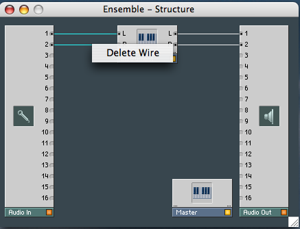
1. Start up Reaktor, click on File and choose New Ensemble
from the drop-down menu. Right click on the Instrument in the centre
and look at its Properties… there you’ll find an
explanation of what it is (you may need to click on the
“i” pane). Break the feedback loop by deleting the
two input connections (if you haven’t already).
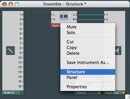
2. Right click on the Instrument again but this time choose Structure.
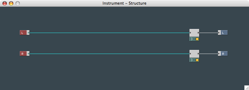
3. Select the two inputs and their connectors and press Delete, to
leave you with an empty instrument.
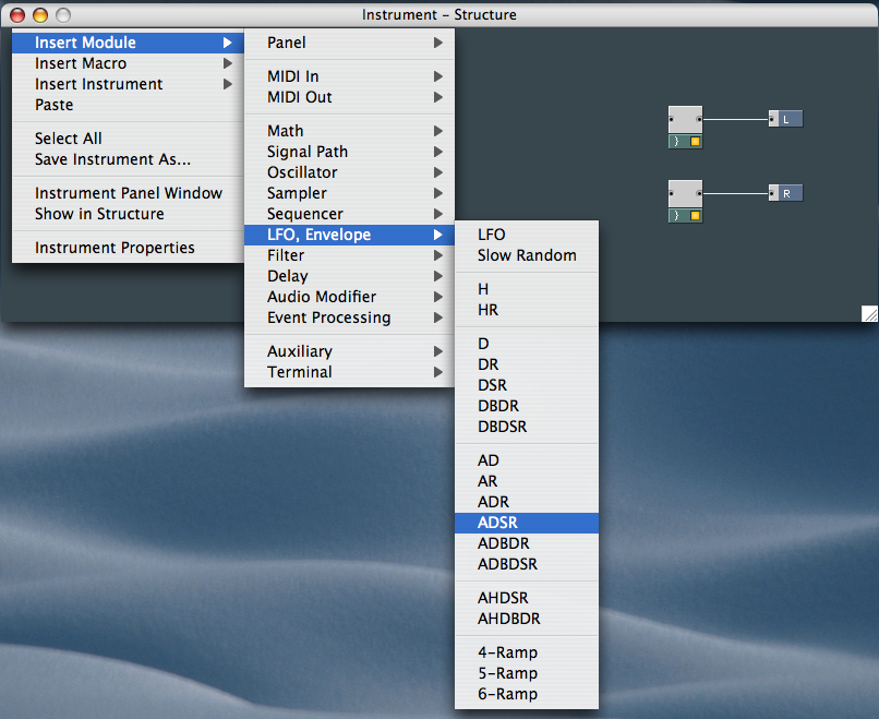
4. Expand the Structure screen to full size because there's quite a bit
to fit into it. For starters, you need an envelope for the oscillators
so you can control the Attack, Decay, Sustain and Release. Right-click
and select Insert Module/LFO, Envelope/ADSR from the menus.
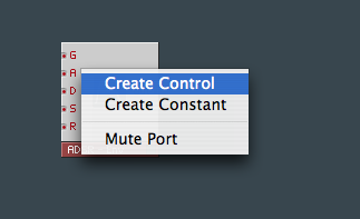
5. Now you need to create the controls for the envelope. Right-clicking
on the A of the envelope brings up the
option to create a control; clicking this to create a controller
attached to the input A. You need do the
same for the Decay, Sustain
and Release.
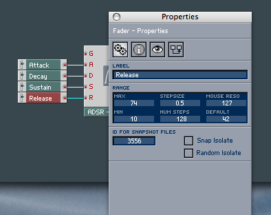
6. You now need to set how much a control's movement will affect the
envelope. Right-clicking on a control calls up its properties (you may
need to click on the “tools” pane); leave sustain
as it is and change the others' control ranges to 74 Max and 10 Min
with a Stepsize of 0.5, then click on the “eye”
tab, select the Small and Vertical
Fader buttons and close the Properties box.
7. The synth has to 'know' when a key is being pressed, so you'll need
to connect a gate, but you also want it to know which key is being
played and to understand any pitchbend commands. Call up the menus and
go to Insert Module/Midi In to create Gate, Pitchbend and Notepitch
MIDI events.
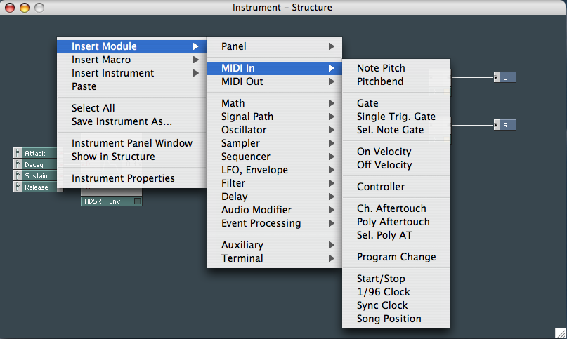
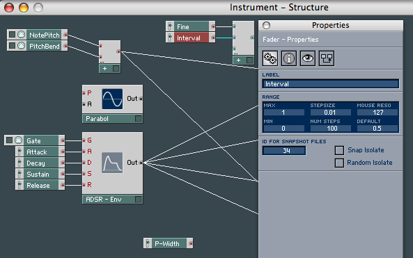
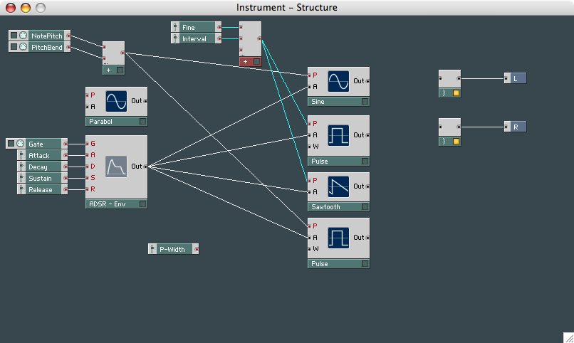
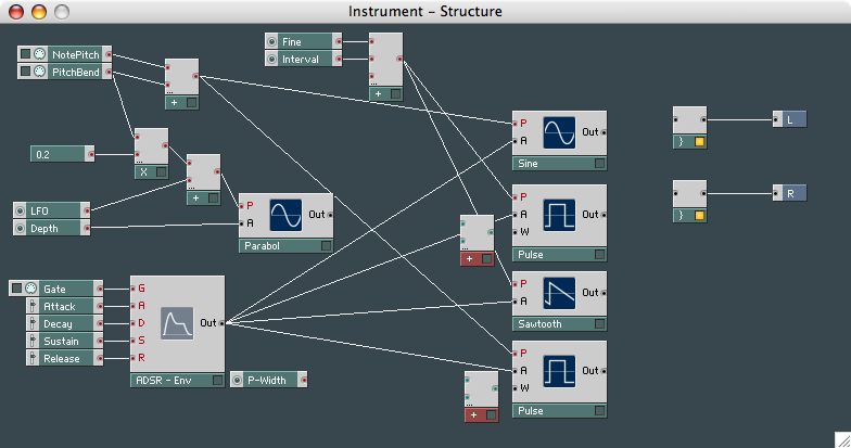
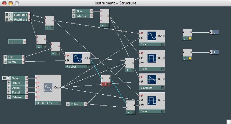
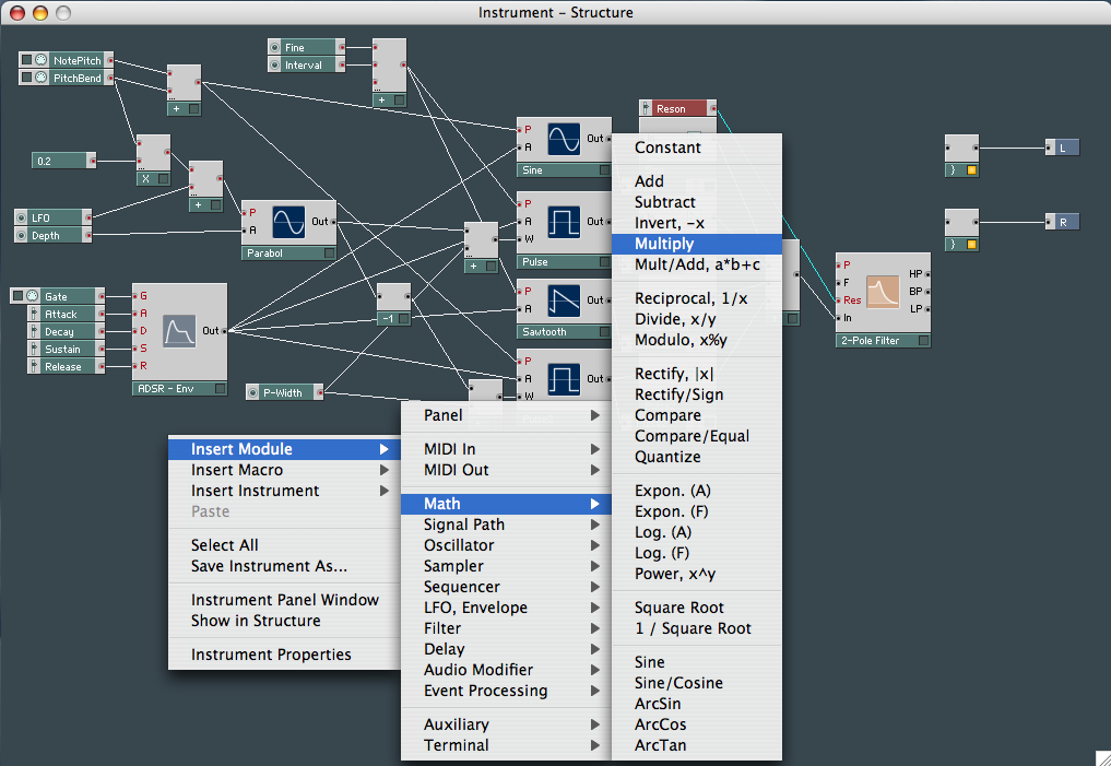
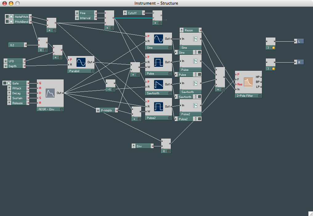
8. At this stage, your synth should look like this:
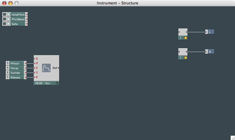
9. Now you need to 'wire' the gate into the envelope generator and move
Notepitch and Pitchbend out of the way while you choose your
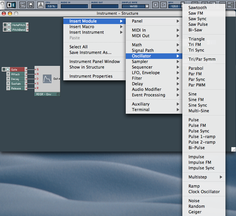
oscillators. Right-click anywhere in the Structure field, go Insert
Module/Oscillator and select a Sawtooth, a Sine, two Pulse waves and a
Parabol wave.
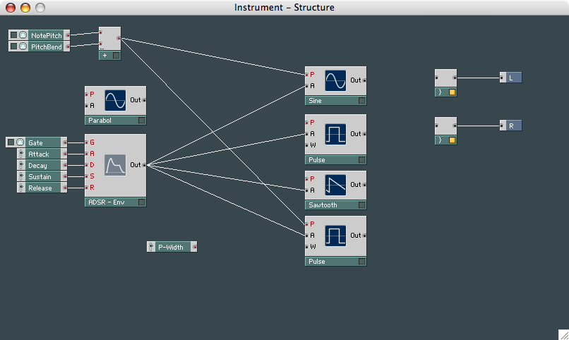
10. Wire the output of the envelope generator into the Amplitude
input of only four of the oscillators. The Parabol wave is going to be
used as the LFO source to add a 'wobble' effect. Create a control for
the Width of a Pulse oscillator and then
delete the connecting wire.

11. The oscillators still have no way of identifying the pitch of the
note, or the Pitchbend. You need to 'add' these two 'events' together
before connecting them to the Pitch input
of two oscillators. Choose Insert Module/Math from the menu, select Add
and connect them.
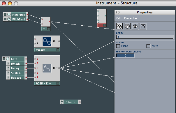
12. You'll want to be able to adjust the tuning between some of the
oscillators, so you'll need to create a 3 Event Adder. Use Copy and
Paste to create a second 2 event adder, right-click on it, select
Properties and switch to the “tools” pane if
necessary. Change “MIN NUM PORT GROUPS” to 3.
13. Create controls by right-clicking on tle inputs and, using the
Properties box again, name one 'Fine' with ranges of 0.64 max and 0
min, and stepsize 0.005, and just name the second 'Interval'.
14. Choosing a low range for Fine and keeping the Interval at a large
range gives you plenty of control for detuning the two remaining
oscillators. Now connect the output of the 3 Event Adder to the Pitch
input of the two remaining (Pulse and Sawtooth) oscillators.
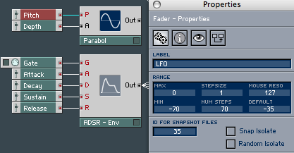
You need to create controllers for the LFO. Using your Parabol wave as
the source, you need to create controls by right-clicking on its
inputs. Rename Pitch to LFO and set its
range to -70 min, 0 max, with 1 Stepsize, and Ampl
just needs renaming to Depth.
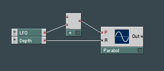
16. The LFO also needs to identify with NotePitch and Pitchbend, so it
works at the same frequency as the note being played. Again, LFO is an
event, so you need to use a 2 Event Adder. Call it up from Insert
Modules/Math list and use it to replace the LFO to Pitch connector.
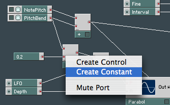
17. You'll need to multiply the Pitchbend controlling the LFO with a
constant event value, so the LFO will stay at a constant rate with
Pitchbend. Call up Insert Module/Math/Multiply and wire it up as shown.
Now right-click the other connector and create a Constant. Use the
Properties box to give your constant a value of 0.2. Make sure
it’s the value you change, and not just the label. If you
give it a higher value than this, the LFO will become too
‘grainy’.
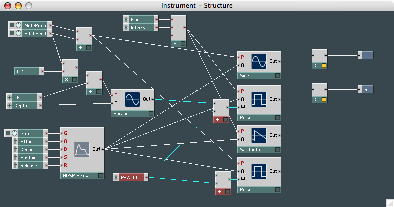
18. Now you need to connect the Parabol LFO to the Width
controls of the Pulse oscillators, so create two more 2 Event Adders.
19. The Pulse Width control controls the 'width' of the oscillations
(giving a more hollow sound), but it's also controlled with the LFO.
Wire the output of the LFO Parabol wave into the top audio connector,
and then wire up the as yet unused P-Width controller to both 2 Event
Adders. Don’t forget to connect the output of the Adders to
the Width inputs of the two Pulse
oscillators. The connections you need are highlighted in the picture
below:
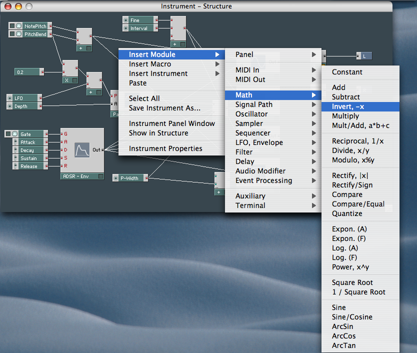
20. You don't want the same LFO effect on both pulse waves - they'd
cancel each other out - so you'll need to use an audio inverter. This
will reverse the LFO signal to the second pulse wave, causing them to
'beat' against each other. Go Insert Modules/Math/ and select Invert,
-x.
21. Connect the LFO (Parabol oscillator) output into the inverter, then
into the Audio Adder, though to the Width
input of the second Pulse oscillator. Now all you need is a filter to
sweep it all, and a few other small additions.
Constructing a Modular Synth, Part 2
For the second, concluding part
of this tutorial on synth building, we'll be concentrating on adding a
filter to sweep the sound, as well as a few more controls and switches
for a more tweakable, 'hands on' experience.
After oscillators, filters are the next most important feature in a
synth designer's sonic arsenal. When it comes to creating and editing
sounds, it's vitally important that you offer as much control as
possible over them. A separate envelope can be used to control the
filter, but in this example we're going to be using the same envelope
that controls the oscillators, as this will allow the filter to change
with any movements of the envelope's controls, preventing it from
drifting out of sync.
Effects also play an important part in how the finished synth will
sound. In the example on the following pages we've used a stereo
phaser, but it's worthwhile experimenting with all the other effects
Reaktor has to offer.
Although there are no hard and fast rules to follow when you are
building a synth, it is important to follow a basic structure. Once you
understand this basic structure, building more complex synths will soon
become second nature, and the beauty of Reaktor is that, if you're not
happy with the results, you can just wipe the slate clean without it
costing a fortune in solder and parts. You can, therefore, be as
adventurous as you like.
Try using different oscillators in place of the ones we're using here,
or different filter combinations. Remember: it's your synth and it's
there to be used and abused. You'll only get out of it what you put
into it - a bit like a relationship really...
So take the phone off the hook, settle down in front of your machine
and we shall begin...
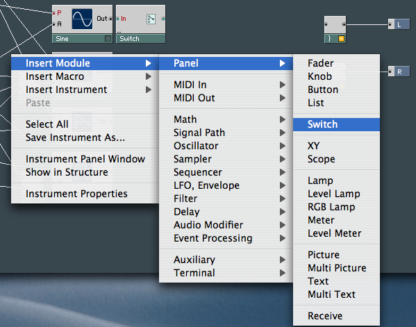
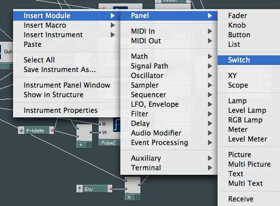
22. We'll start by adding switches to the four oscillators
from last month, so when you design sounds on your new synth you can
choose which oscillators you want to use to create a sound. Right-click
anywhere in the structure and choose Insert Modules/Panel/Switch.
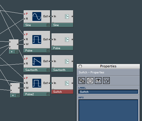
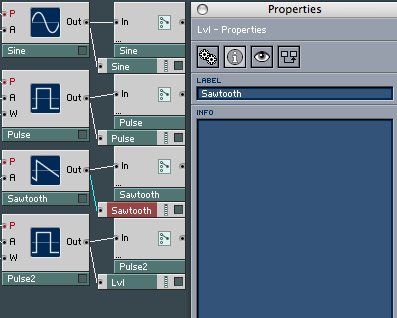
23. You need to create four switches (one for each
oscillator). Wire each switch to each of the four oscillators, and then
right-click on the first switch in turn to call up the Properties box.
Rename the switch appropriately and then, without closing the
Properties box, click on the next switch. You’ll see the
Properties box change. Rename the other switches. You might also like
to rename one of the Pulse oscillators.
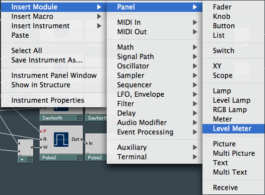
24. To make sure each oscillator is giving a signal, attach a
level meter so that when using the Instrument Control Panel, you
immediately see which you're using to make the sound. Right-click and
select Insert Modules/Panel/Level Meter. Create one for each oscillator.
25. Place the level lamps under each of the four switches you
created earlier and connect the output of the oscillators to the inputs
of each of the level lamps. Right-click on each level lamp to call up
its properties and name each one after its associated oscillator.
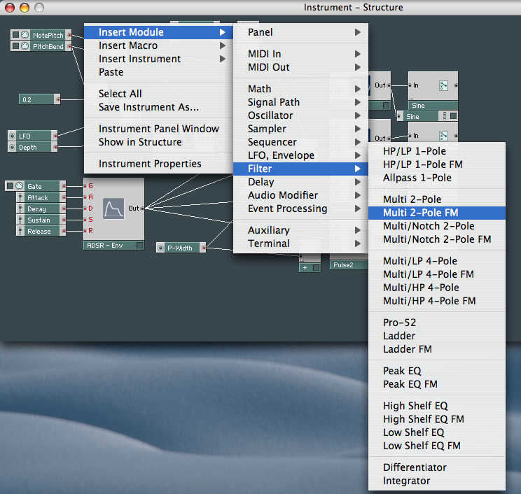
26. Now it's time to add a filter to the synth. In this
example it's a multi two-pole FM filter. This offers Highpass, Bandpass
and Lowpass control, giving plenty of filter control over the final
sound of the synth. Right-click and select Insert Module/Filter/Multi-2
Pole FM.
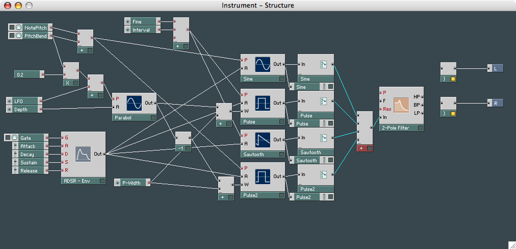
27. You'll need to 'join' the outputs of the four oscillators
into one signal, as the filter only has one input. Look back to step 12
and create a 4 Event Adder. Place the newly created 4 Event Adder in
between the filter and the oscillator switches you created earlier.
Wire the output of each switch into each of Adder's inputs and then
wire the Adder's output to the input of the two-pole filter.
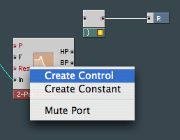
28. You need a way of controlling the filter. Right-clicking
on any input of the filter will allow you to create a control, but only
a resonance control is needed, as the other inputs are going to be
controlled by the envelope we created in steps 4-6. Therefore, just
create a resonance control.
29. As the synth's filter is going to be controlled with the
same envelope which controls the oscillators, you need to be able to
control how much this envelope will affect the filter. Right-click and
select Insert Modules/Math and select Multiply from the menu.
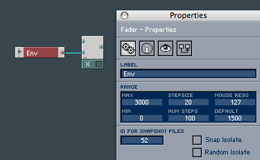
30. Right-click on one of the inputs of the newly created
Multiply and create a control. Right-click on this new control to
access the Properties box, then name it 'Env' and give it a max value
0f 3000, a min of 0 and a stepsize of 20.
31. Connect the output of the ADSR envelope to the other input
of the Multiply, and then connect its output to the filter input of the
two-pole filter. The reason for this is that the filter will sweep in
time with the oscillators as both are controlled by the same envelope.
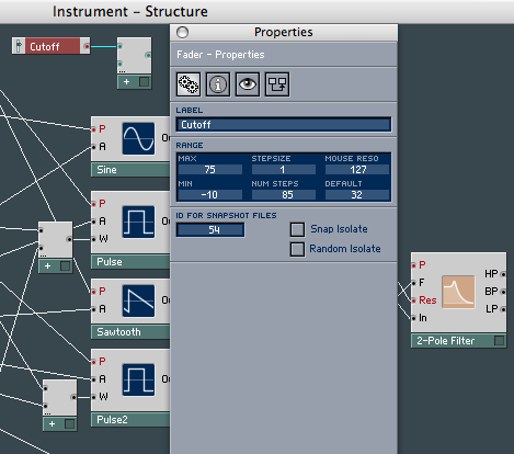
32. There's still no control over the amount of frequencies
that can get through, so you'll need to create a filter cutoff knob.
Select Insert Module/Math/Add from the menu and create one control for
it. Name this control it 'Cutoff', with values of 75 max, -10 min and
stepsize of 1.
33. The cutoff must be able to detect which note on the
keyboard is being played for it to work effectively and sweep the
correct frequencies, so you need to associate it with the Notepitch and
Pitchbend events. Connect the sum of these two MIDI events to the 3
Event Adder you created in step 12.

34. This gives the two oscillators (Sawtooth and Pulse) that
are connected by the 3 Event Adder Notepitch and Pitchbend
compatibility, and by connecting the output of this 3 Event Adder to
the input of your recently created Cutoff event, it also gives the
Cutoff a pitch to work with.
35. Connect the output of the Cutoff events to the Pitch input
of the filter to complete the filters circuit. The filter has three
outputs - Highpass, Bandpass and Lowpass - and you'll want to be able
to switch between the three, so call up the menu and select Insert
Module/Panel/Switch.
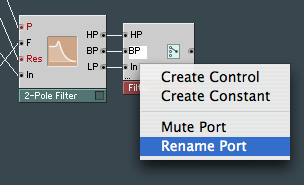
36. In the Switch’s Properties box, change MIN NUM
PORT GROUPS to 3 name the switch ‘Filter’. Each of
these inputs will need naming, so that you'll know which switch to use
for which filter effect in the instruments panel, so Right-click on
each, choose Rename Port and name each by its wired counterpart.
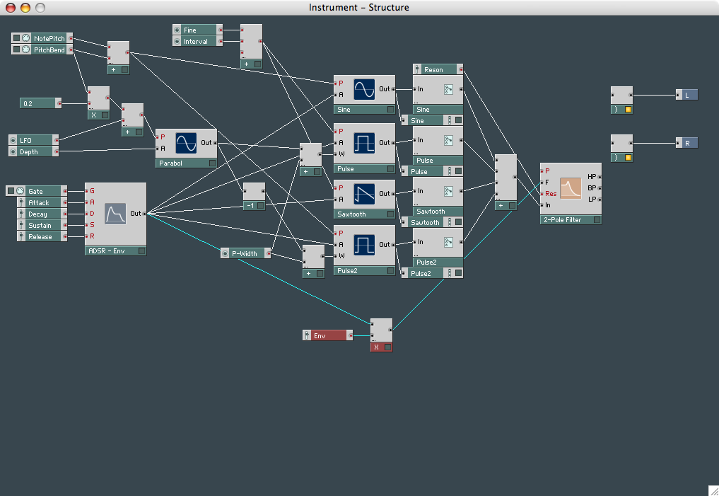
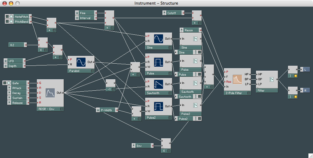
37. All that's left to finish off the instrument is to connect
the output of the filter to the outputs of the instrument.
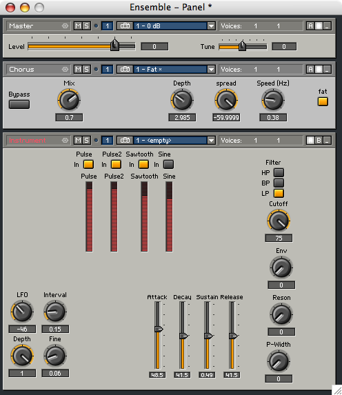
38. Close the Instruments window and open the
Instrument’s Control Panel in the Ensemble – Panel
window. Click to the right of the Instrument label (the icon changes to
a spanner). Now organise it so you are comfortable with its layout.
Right-click in the Ensemble - Structure window to bring up the effects.
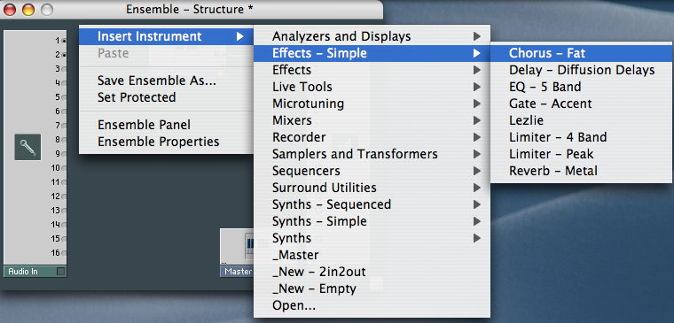
39. Choose any effect you want to use - here it's a fat
chorus. Adjust the wiring so that your Instrument signal passes through
your chosen effect. That’s it. Now you need to change things
around, better to understand how it all works.