Symple Synth: Low Frequency Oscillator
Next we're going to add some vibrato (low frequency variation in frequency and/or amplitude).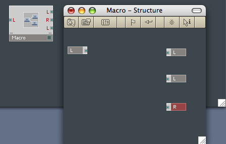 1. First we'll keep
things neat and easy to follow by making a container for our LFO. Right
click and
select Macro>_New 2in2out and open the Structure Window of the
new Macro. Delete one of the input ports and add an output port (using
Copy/Paste is the quickest way)
1. First we'll keep
things neat and easy to follow by making a container for our LFO. Right
click and
select Macro>_New 2in2out and open the Structure Window of the
new Macro. Delete one of the input ports and add an output port (using
Copy/Paste is the quickest way)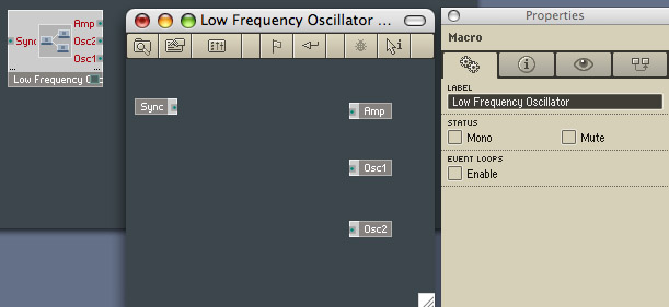 2. Use the
Properties Dialog to rename the Macro to "Low Frequency Oscillator".
The input port is going to carry the signal from the Gate so that the
LFO is synchronised with the Oscillators, so rename the Input Port to
Sync. The three output ports are going to allow us to route the signal
to any (or all) of Oscillator 1 Pitch, Oscillator 2 Pitch and
Amplitude. So let's rename them whilst we've got the Properties Dialog
to hand.
2. Use the
Properties Dialog to rename the Macro to "Low Frequency Oscillator".
The input port is going to carry the signal from the Gate so that the
LFO is synchronised with the Oscillators, so rename the Input Port to
Sync. The three output ports are going to allow us to route the signal
to any (or all) of Oscillator 1 Pitch, Oscillator 2 Pitch and
Amplitude. So let's rename them whilst we've got the Properties Dialog
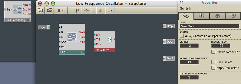
to hand.3. Now
for the LFO
itself. Right
click and
select Built-In Module>LFO, Envelope>LFO. As you will see
if you check its Properties, this LFO will provide us with three
different waveforms at the same time. We're going to put a switch in
there so that we just use one at a time. Right click and select
Built-In Module>Panel>Switch. Use the Properties Dialog
to rename the Switch to "Waveform" and to change MIN NUM PORT GROUPS
from 1 to 3. For clarity in the control panel, let's also rename the
inputs of the Switch to "Sin", "Tri" and "Pls".
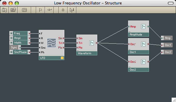 4. We've added a Switch
to select which waveform the LFO should use. Now we'll add a switching
system to target the LFO's output. We want it to be able to affect any
one or two or all three of the Pitch of Oscillators 1 and 2 and the
output Amplitude. So we'll need three simple switches, Labelled
"Amplitude", "Osc1" and "Osc2". To complete the LFO, Create Controllers
for the LFO's inputs (except the Sync, which we've already created) and
wire it all up.
4. We've added a Switch
to select which waveform the LFO should use. Now we'll add a switching
system to target the LFO's output. We want it to be able to affect any
one or two or all three of the Pitch of Oscillators 1 and 2 and the
output Amplitude. So we'll need three simple switches, Labelled
"Amplitude", "Osc1" and "Osc2". To complete the LFO, Create Controllers
for the LFO's inputs (except the Sync, which we've already created) and
wire it all up.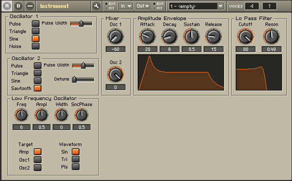 5. Before we connect up the
LFO, let's tidy up the panel. First we'll unlock it and arrange things
to look like the picture on the left. You'll notice that the set of
three Switches has a label in the picture - that's a bit of a cheat!
I've just right clicked in the Panel and used Insert Built-In
Module>Text. Then in the Text's Properties Dialog I've changed
"Enter your text here!" to Target, unchecked "Label" on the Visble pane
and changed the style from Flat to Transparent.
5. Before we connect up the
LFO, let's tidy up the panel. First we'll unlock it and arrange things
to look like the picture on the left. You'll notice that the set of
three Switches has a label in the picture - that's a bit of a cheat!
I've just right clicked in the Panel and used Insert Built-In
Module>Text. Then in the Text's Properties Dialog I've changed
"Enter your text here!" to Target, unchecked "Label" on the Visble pane
and changed the style from Flat to Transparent.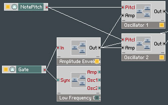 6. Now
let's connect it all up. And we'll add some pitch bend into the
bargain. Take an extra output from the Gate to the LFO's "Sync" input.
6. Now
let's connect it all up. And we'll add some pitch bend into the
bargain. Take an extra output from the Gate to the LFO's "Sync" input.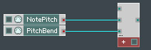 7. Right click and
select Built-In Module>MIDI In>Pitchbend. We'll need to
add the Picthbend to NotePitch so Right click and select
Built-In Module>Math>Add. In the Properties Dialog of the
Add module change MIN NUM PORT GROUPS to 3 (we'll need the third one
later) and connect the Notepitch and Pitchbend to the Add module.
7. Right click and
select Built-In Module>MIDI In>Pitchbend. We'll need to
add the Picthbend to NotePitch so Right click and select
Built-In Module>Math>Add. In the Properties Dialog of the
Add module change MIN NUM PORT GROUPS to 3 (we'll need the third one
later) and connect the Notepitch and Pitchbend to the Add module.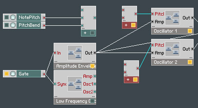 8. Our LFO pitch
information for each oscillator needs to be added to this incoming
Pitch and Pitchbend information. So create two more Add modules and
wire them in to the Pitch inputs of the Oscillators
8. Our LFO pitch
information for each oscillator needs to be added to this incoming
Pitch and Pitchbend information. So create two more Add modules and
wire them in to the Pitch inputs of the Oscillators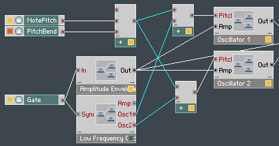 9. Now
wire the Notepitch/Pitchbend Add module output to each of the
Oscillator Add modules and wire the relevant LFO Osc outputs to the
Oscillator Add modules too. I've highlighted the new wiring.
9. Now
wire the Notepitch/Pitchbend Add module output to each of the
Oscillator Add modules and wire the relevant LFO Osc outputs to the
Oscillator Add modules too. I've highlighted the new wiring.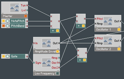 10. Finally, as far as
pitch is concerned, cut and paste the Master controls (from the top
level) into your Instrument and add the output of the Master Tuning to
the spare input of the first Add module we made.
10. Finally, as far as
pitch is concerned, cut and paste the Master controls (from the top
level) into your Instrument and add the output of the Master Tuning to
the spare input of the first Add module we made.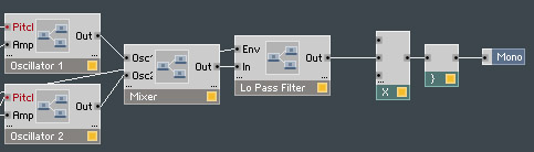 11. Amplitude is a little
more complex - we'll have to compensate for levels as we add and
multiply things together. Right click and select Built-In
Module>Math>Multiply with MIN NUM PORT GROUPS 3 and place
it across the output.
11. Amplitude is a little
more complex - we'll have to compensate for levels as we add and
multiply things together. Right click and select Built-In
Module>Math>Multiply with MIN NUM PORT GROUPS 3 and place
it across the output.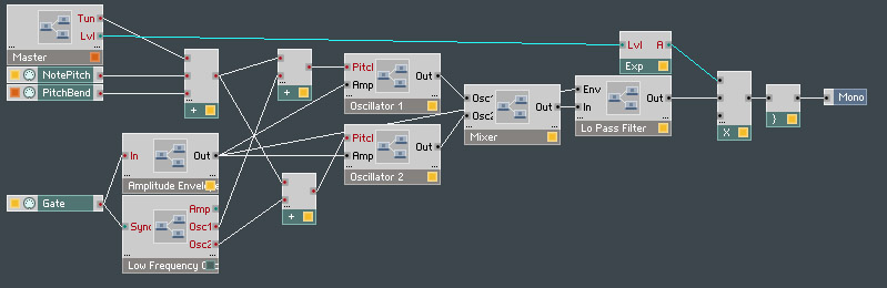
12. To
convert the Master Level, right click and select Built-In
Module>Math>Expon. (A). This converts the logarithmic
level values produced by the Master Level to the linear Amplitude
values we need. Wire the Master Level output through the Exponentiator
to our Multiply module.
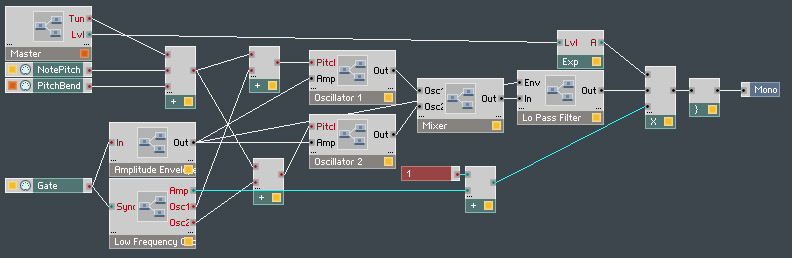
13.
Create one final Add module, right click one of its input ports and
Create a Constant with the value "1". Wire the Amp Output of the LFO
into the other input port and wire the output port to the Multiply
module.
That's
it, we're done with the
noise-making part. Let's add a scope
so that we can
'see' the wave we're producing